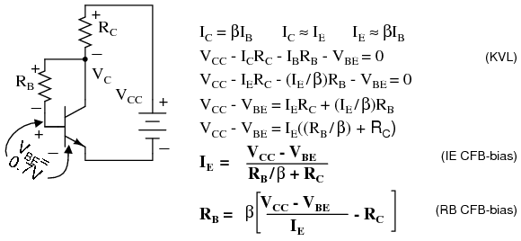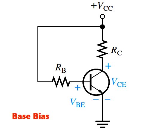


You know the voltages before and after C c. Now, if you want to design an amplifier to give an output ac voltage of 10 V peak, what bias voltage would you prefer? Is your answer equal to 10 V? Oh, no problem, we’ll figure it out step by step. If C c is removed, the output voltage V out gets a DC shift of V cc voltage. In Figure.1, the coupling capacitors C i and C c are included to block the DC components from the input and output respectively. With all accounted for, you should be sitting at no voltage. Now combine this concept with negative half cycle and instants where V in < 0.7. We know that EB junction remains FB for only the instantaneous values of V in > 0.7 V (EB voltage drop) and otherwise RB. The voltage drop I CR L gives the ac output voltage V out.ĭo you think amplification is possible without DC bias? If so, disconnect V cc from the base and predict V out. The current gain denoted by in the transistor datasheet is the proportionality constant in the I c - I B relationship. The relationship given in Table.2 for the CE amplifier is obeyed and I c follows the shape of I B. When an ac signal V in is superimposed with the bias voltage V CC, it similarly varies I B with respect to time. The E and C junctions can be supplied from a single dc voltage V cc as it fulfills the major purpose of supplying the input transistor current. Let’s catch a CE silicon NPN transistor amplifier (shown in Figure.1) in action. Normally, the transistor amplifier shares a common terminal between its input and output and the three possible configurations are given in Table.2.

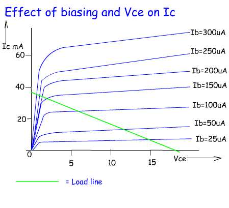
The Secret Behind the Transistor Amplifier We are discussing transistor biasing in the context of a transistor amplifier. The biasing circuits for transistor switches are generally called base drive circuits. Table.1 The region of operation and bias conditions in a transistor Table.1 gives details about the region of operation and bias conditions at emitter and collector junctions when a transistor operates as an analog and digital device. The biasing for a transistor to operate in an amplifier is entirely different from that in a transistor-based converter. The biasing applied to the two PN junctions of the transistor influences the movement of majority carriers and thus the behavior of the transistor. This dual action of the transistor is realized by transistor biasing. or a digital device in converters and switching circuits. The Bipolar Junction Transistor (BJT) operates as either an analog device in applications such as amplifiers, oscillators, etc. Let’s see how biasing defines the transistor operation. Whatever be the application, a stabilized DC bias is a must for proper transistor functioning. The transistor acts exactly like a dead phone when there is no DC bias. Transistor biasing (DC biasing) is the process of providing appropriate DC voltage or current to a transistor for its proper functioning in an electronic circuit. This situation can be well mapped to a transistor without proper transistor biasing. Fortunately, her battery died and I was saved. After a few minutes, I was ready to end the conversation, but there was no sign of anything stopping her from the endless lectures. She kicked off a long one-sided conversation mixed with complaints and bits of advice on my busy schedule, health, kids, etc. Yesterday, I happened to dial my aunt after a really long gap. If you vary the transistor bias voltage, the Q-point will also shift its position.Ī phone with a dead battery is like a transistor that has not been properly biased The optimum value of transistor bias voltage is equal to two times the required AC output voltage peak.

Without transistor biasing, BJT amplifiers fail to deliver the required output across load terminals. Transistor biasing makes analog and digital operation of a transistor possible.


 0 kommentar(er)
